Intelligent Sensors Knowledge Base
I noticed you have a 5 dry contact sensor for the sensorProbe2, do you have a wiring diagram of this and which color of wires represents which RJ-45 connection?
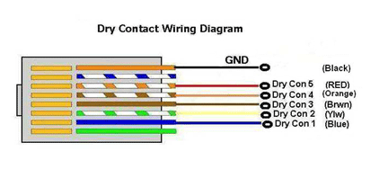
5 Dry Contact Sensor Pin-Out Diagram
Yes, this is the wiring diagram for the 5 Dry Contact Sensor below.
If I have a rely setup on my RJ-45 dry contact sensor is there a way to cycle this and If so, how do I do that?
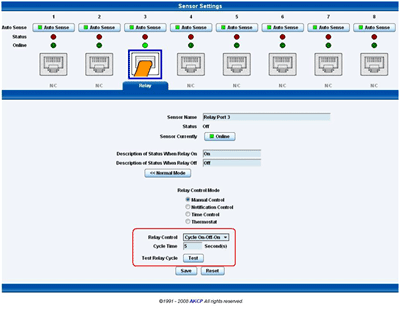
You have two options for cycling the relay on the dry contact sensor. The first one is from the web interface as shown in the screen shot below.
I have a burglar alarm system that needs 12V and I want to control this with my sensorProbe8 and my dry RJ-45 dry contact sensor, how do I do that?
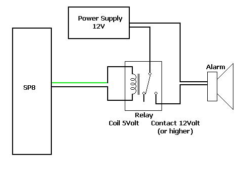
12V burglar alarm system on dry contacts sensorProbe8-X20? You can integrate the dry contact output from the unit to his burglar alarm system by using a 12V power supply and a relay.
The relay can then drive the +5V from dry contact sensor to the 12V burglar alarm system.
What is the best way I can trouble shoot a sensor if I think it is faulty?
How to trouble shoot AKCP sensor if suspected faulty? The simplest way to determine if you have a faulty sensor is to try connecting it to another RJ45 port on your unit. If you have the sensor extended with additional CAT5 cable then try connecting the sensor directly to the unit (without the extension cable) Make sure the autosense feature is enabled on this port. You can also try rebooting the unit ensure that unit is running the latest version of the firmware. If you still have problems please contact support@akcp.com
If I suspect I have a bad sensor, how long is the warranty and what should I do?
Unless you purchased and extended warranty, this period is one year after the purchase date. The RMA process begins with you contacting AKCPs Support Team at support@akcp.com who will determine if the sensor is faulty. Please include the sensors serial number when contact the AKCP Support Team If the sensor is determined to be faulty and is confirmed to still be covered under your warranty plan, then AKCP will provide you a replacement at no cost Please contact the AKCP Support Team for instructions on the RMA process
Do I have to send my faulty sensor back to AKCP?
No, you do not have to ship the sensor back to us, however because of this, we do require that you send us proof that you have destroyed the faulty sensor. A digital picture is sufficient for this
What if my sensor is not covered under my warranty plan any longer? Will AKCP offer me a discount if I want to purchase a replacement sensor?
Yes, AKCP offers a lifetime 50% discount off the current list price of the sensor, if you wish to purchase a replacement. We again require that you provide us with proof that you have destroyed the faulty sensor
Can your 5 dry contact sensor for the sensorProbe2 be configured as inputs and outputs?
No, the 5 Dry Contact Sensor can only be configured as inputs. The regular single RJ-45 Intelligent Dry Contact Sensor can be configured as both an input and output.
Can your single dry contact RJ-45 sensor measure voltage, or how does it work? Why does it show in my web interface as a security sensor?
Our RJ-45 single Dry Contact Sensor is a switch type sensor, so it does not measure voltage, it is either on or off. You can configure this as either an input (normal state is closed GND, or Open/+5V), or an output (set level to either a Low/GND, or a High/+5V). You have to turn off the auto sense feature and configure the sensor (manually) so that this is a relay on the port and not a security sensor, which the units web interface will show after it is plugged in.
Regarding your single dry contact RJ-45 sensor, can you please confirm the pin-out information for a dry contact that connects to one of the dry contact ports, also which pin supplies power (pin1, 5v,)?
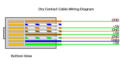
Here is the pin-out for the dry contact sensor. The RJ-45 the combination is: White/orange, orange, white/green, blue, white/blue, green, white/brown, brown.
On the sensor on the black wire: white/green , green and brown. On the red wire: only orange, the rest are cut off. Please see these diagrams below. it is the same sequence for the security sensor the difference is the screwing with the blue lugs.
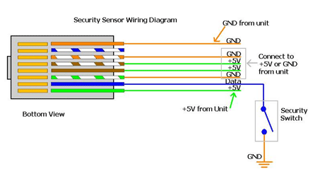
Is it possible to connect my securitySensor up in series, if I wanted to monitor a number of doors in the same building for example? If so, how do I do that?
Yes, the securitySensor can actually be wired in sequence. You can take the contact from one security sensor and wire it to the next. The only limit to the number of sensors you can have in series is the maximum run length of the Security Sensor, which is 300 meters, or about 1,000 feet. You have a couple options. You can connect the security sensor, from each door to each extra dry contact input (X20). The advantage of this solution is that if you have 20 doors you can label each one individually and see which one has triggered. With them wired in sequence you will know a door has opened but not which door.
Is it possible to setup my RJ-45 dry contact sensor as a relay, If so, how do I do that?
Yes, You can use one of our RJ-45 dry contact sensors in the any of the 8 ports to drive a relay and a temperature sensor to trigger the output to the relay. The dry contact sensor can be configured to output +5 VDC. You have to turn off the auto sense feature and tell the unit (manually) that this is a relay on the port and not a ?security? sensor, which the units web interface will show after it is plugged in. At this point, you would configure the temperature thresholds and create the relay action and link the sensor to the relay. When the unit turns the ?relay? on, you will get 5VDC output to the dry contact. This can also be used to drive a mini solenoid switch or something like that to turn on a larger circuit.
I am sure that all settings for the Digital Voltmeter sensor are correct, but it seems to have error in the reading. How can I correct this error?
The Digital Voltmeter and 4-20mA sensors have an input as analog signal which will be converted to digital using an A/D converter. Normally, the A/D converter is calibrated in production process. But, you also can do it by following the steps below. On the web interface, turn off an Autosense for port#1. To do this, Go to the Sensor setting on the web interface by clicking on a ?Sensor? tab. On the bottom of the left side menu, click on ?Autosense?. Select ?Disable? for the port# 1. Then, click ?Save?. Connect 1.25VDC to RJ45 port# 1. The 1.25V is the voltage across pin 7 and 8 of the cable plugged into the RJ45 port. Set a Digital Voltmeter sensor online on this port. We only focus on a Raw Analog, so you do not need to change any settings. a. Go to the setting page of the DC sensor at port# 1. Select ?Online? for Go Online/Offline field. Then, click ?Save?. Run snmpset command as snmpset .1.3.6.1.4.1.3854.1.2.2.1.80.0 i 0 Replace with the IP address of your sensorProbe, and with the administrator password. The raw analog reading from the web interface should read 500 (+/-5). Please note that all RJ45 ports use the same A/D converter. Therefore, the calibration on any port will also have an effect for other ports. And, an error for each sensor is different due to components (e.g. resistors, capacitors) on the sensor. So, it is possible that the same input value will not be read the same for different sensors on the same sensorProbe.
I just finished a calibration process, but the reading is still a little bit off. Is there any way to fine tune the reading?
In the calibration process, we set the offset of the reference voltage so that the raw analog read 500 when the input to the RJ45 port is 1.25 volts. However, the sensor that you are using may still have error due to some components (e.g. resistors and capacitors). Run snmpset command as: snmpset .1.3.6.1.4.1.3854.1.2.2.1.96. i where * is the IP address of your sensorProbe. * is the administrator password. * is the port number where the sensor for which you want to adjust the offset is plugged in. * is the offset value. It should be in a range from 485 to 515. Do you have any sensor that is capable of reading the fluctuation of electricity, and send me reports? Yes, we have a sensor that is capable of monitoring Voltage, Wattage and Amperage. This is our Power Meter Sensor. You can set alerts as with our other sensors so that you can receive a notification when electricity fluctuates beyond a preset threshold. Please see the product section of our web site for more specific information about this sensor
Do you have any sensor that is capable of reading the fluctuation of electricity, and send me reports?
How to monitor electricity fluctuations? We have a sensor that is capable of monitoring Voltage, Wattage and Amperage. This is our Power Meter Sensor. You can set alerts as with our other sensors so that you can receive a notification when electricity fluctuates beyond a preset threshold. Please see the product section of our web site for more specific information about this sensor
I noticed you have an airflow sensor, can you tell me how can I utilize this sensor in my environment to help prevent problems?
The AKCP airflow sensor is designed for systems that generate heat in the course of their operation and a steady flow of air is necessary to dissipate this heat generated. System reliability and safety could be jeopardized if this cooling airflow stops.
Can you please explain how your airflow sensor works?
The way the air flow sensor works is there are two thermistors, one internal and one external. A thermistor changes resistance based on air temperature. The internal thermistor is the reference point and the external thermistor changes when the airflow is blown across the top of the sensor, the difference is this raw output reading. Then the raw output reading is calculated into the presence or absence of airflow.
How accurate is your airflow sensor?
The airflow sensor is not a precision measuring instrument. This device is meant to measure the presence or the absence of air flow. The placement of the sensor is very important as well as this should be placed so that the airflow flows over the top of the sensor.
Is it possible to extend the run length of my sensors?
Yes, you can extend the run length of your sensors, but each sensor has its own maximum, so please contact the AKCP Support Team about your specific sensor. Also remember that the length you can extend up to can be affected by electromagnetic interference from other appliances. If for example the extended UTP cable is running through a false ceiling next to fluorescent tube lights it can have an adverse effect on the range you can extend up to.
I have one of you DC Voltmeter sensors and my question was can this sensor handle DC signals from 0 to 10 mV?
What is the resolution of the AKCP DC Voltmeter? The lowest signal will be 0.1V (100mV). We display only the one decimal place in the web interface of the unit. If the input signal is less than 0.1V it will display 0.0V.
Do I have to use a special type of cable to extend the run length of my sensors?
You can use any type, or brand of standard CAT5/6 UTP LAN cable to extend your sensors. We recommend however for longer lengths to use a high quality, low impedance branded CAT5/6 cable.
What is the internal impedance of your DC Voltmeter sensors?
Our Digital Volt meter has an input impedance of 2M ohms (2,000,000 ohms).
If I do extend the run length of my sensors, for example my temperature/humidity sensor, does this affect the reading and accuracy of the sensor?
Does extending the sensor will it affect the reading? All temperature and humidity communications are 100% digital with no loss of accuracy regardless of the length. There is an A/d converter, CPU and communications subsystems all located within the sensor itself.
I noticed you have a 5 dry contact sensor for the sensorProbe2, what is the OID for this sensor?
You would use the same OID for the 5 dry contact sensor as you would for the switch sensor type or single dry contact sensor. You can download our OID manual for your reference from our web site at the customer login page.
I see you have two types of temperature and the dual temperature humidity sensors, can I extend both of them?
Yes, we offer two types of these sensors. The TMP01 and THS01 are the fixed one foot type and are only designed to be connected directly to the AKCP base unit and NOT to be extended as it says in the product data sheet. If you need to extend the sensors then you need to use the remote type or TMP00 and THS00 (box type).
Can I connect these sensors through my RJ-45 CAT5/6 patch panels? Can I use those female to female CAT5 RJ-45 couplers to extend them?
No, we do not recommend you trying to connect any of our AKCP sensors including the temperature and dual temp humidity sensors though patch panels or using the RJ-45 couplers to extend them. You may find that this works, however it will be very inconsistent and this is due to the signal strength from the sensor to the base unit. The resistance of the extra connectors in a patch panel, or couplers is often enough to prevent the sensor from working.
Can AKCP provide me with the wiring diagrams for each sensor I have?
Wiring diagram and pinout for AKCP intelligent sensors? Yes, we have all the wiring diagrams for all of our Intelligent sensors. Please contact the AKCP Support Team at support@akcp.com for these.
Can AKCP provide me with CE certifications for your sensors?
Yes, we have CE certificates for most of our products. You can request them from the AKCP Sales Team at sales@akcp.com, or you can download them from our web site. These are located on each product page.
Can I connect third party sensors to my sensorProbe, or securityProbe?
Yes, actually, one of our greatest strengths is AKCP can provide a data collection center for many different third party sensors. Using our 4-20mA intelligent sensor, we can interface to a wide variety of other types of sensors that output either an analog voltage or a 4-20mA current. For integration with custom sensors, the unit text can be customized to whatever you would like; this text is reflected on the summary page of the web interface. All numbers are displayed in decimal format. On the DC and 4-20mA sensor configuration pages, you can display readings either as absolute values or as a percentage of full scale; you can customize a unit for measured entity. The external sensor used should have an output as a linearized Digital Voltmeter or 4-20mA signal # We suggest you find sensors that will best suit your requirements, and then we will make sure they can integrate with our sensorProbes, or securityProbes. For example we have customers that use our Digital Voltmeter sensor to integrate pressure sensors and water salinity sensors. We even have customers measuring radiation using our sensorProbes. The user can easily input their own labels and output value scales. If you label the sensor output as MPa, sensor values will appear on the summary page and in emails as MPa. You can configure the scale to be absolute such as 0-100 VAC or a percentage such as 0-100%. The data stored and graphs plotted on the sensorProbe will also have the correct labels and scaled units. Note: Emails and SMS will also be displayed in the configured units at the correct scale. 4-20mA signals are very popular in industrial sensors, and are particularly resistant to interference from electromagnetic noise. Note that some sensors and transducers may require an extra power supply, and in some cases may need other electrical components.
Can I connect a third party sensor using the 4-20mA sensor if it outputs more than 5 VDC?
Can I connect third party sensors with 4-20mA sensor? You can apply more than the 5VDC, but you need to be careful not to exceed the 20mA current. The 4-20mA sensor has an internal impedance of 20 Ohms, so if you need to apply, for example 12VDC instead of the 5V, you should then install a resister of 580 Ohms (current will be 20mA). If you were to apply 48VDC, then the resistor should be 2.38K Ohms. You don?t need to install any resister if your third party sensor output is 4-20mA
What is the accuracy of a 4-20mA converter?
The accuracy of our 4-20mA converters is 2%. The resolution of our 4-20mA converters is 0.1mA. You can use these figures in conjunction with your sensor?s accuracy to find the overall precision of your readings. You can also calibrate the 4-20mA converter
